VMT

Videos
Loading the player ...
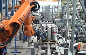
- Offer Profile
- VMT® supplies customised,
turnkey image processing and laser sensor systems and solutions for all
industrial sectors.
VMT solutions are based on our own, self-developed product lines, which cover the entire applications spectrum. As competence center for vision solutions in the Pepperl+Fuchs group, VMT offers absolute high-level technology combined with highest investment security.
Product Portfolio
Inspection
- Completeness check and type recognition with VMT® IS
The core of the system is a neuron network that can be trained to recognize characteristics with the aid of models. This network is trained to recognized model characteristics and symbols, enabling the system to read a liberal number of characteristics.
By adding further appearance variants, the system achieves maximum recognition capability possible. Fluctuations in the surrounding conditions and varying image backgrounds may therefore be easily optimized. The system is an equally effective tool for the end user and the OEM customer in terms of optimized production procedures, process controlling and documenting, thus reducing need for additional and follow-up work.
The unit is operated with a modern user interface that allows intuitive working. No knowledge of programming at all is required to operate the unit.
Through simple movement of the mouse, the user may call up new models and test tasks, change testing plans, or follow trained recognition. Since operation is being kept so simple, one day of training is usually sufficient to be able to operate the system.
Integrated into an automatic sequence VMT IS fulfills its task reliably. In case of irregularities, it is possible, with the aid of statistics and service tools, to analyze the source of the problem and remove the cause. 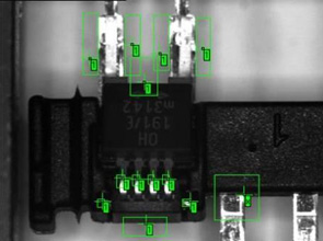
-
- Position, type and completeness check, color verification and processing control
- Type differentiation through combination of several recognized characteristics
- Type recognition with subsequent type-specific inspection
- Suitable also for difficult application conditions, such as changing backgrounds and object properties
-
- Trainable for an unlimited range of characteristics or symbols
- Automatic image memorizing, therefore short operation startup and time optimizing, as well as error documenting
- Accurate verification of the position of characteristics in relation to the current object position
-
- Suitable also for quickly moving objects and high tact rate
- Highest recognition certainty possible through use of preset knowledge of character positions or expected characters, e.g., through use of negative examples and blanking out of irrelevant or disturbing areas
- Owing to swivel/tilting-head cameras, details maybe recognized even on longish test objects and in the largest variety of places.
Code Identification
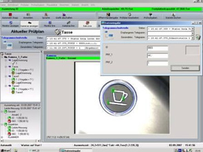
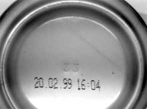
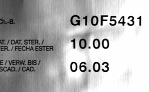
- Optical Character Recognition VMT® OCR
Reading of characters and symbols of all kinds, such as plain text, matrix code and bar code.
The core of the system is a neuron network that can be trained to recognize characteristics with the aid of models. This network is trained to recognized model characteristics and symbols, enabling the system to read a liberal number of characteristics.
By adding further appearance variants, the system achieves maximum recognition capability possible. Fluctuations in the surrounding conditions and varying image backgrounds may therefore be easily optimized.
The system is an equally effective tool for the end user and the OEM customer in terms of optimized production procedures, process controlling and documenting, thus reducing need for additional and follow-up work.
The unit is operated with a modern user interface that allows intuitive working. No knowledge of programming at all is required to operate the unit.
Through simple movement of the mouse, the user may call up new models and test tasks, change testing plans, or follow trained recognition.
Since operation is being kept so simple, two days of training are usually sufficient to be able to operate the system.
Integrated into an automatic sequence VMT OCR fulfills its task reliably. In case of irregularities, it is possible, with the aid of statistics and service tools, to analyze the source of the problem and remove the cause. 
- Suitable also for difficult application conditions, such as changing backgrounds, etc.
- Trainable for a high variety of fonts, characteristics and symbols
- Suitable also for fast moving objects and high tact rates

-
- Automatic image memorizing, allowing short operation startup and time optimizing, as well as error documenting
- Accurate recognition of relevant areas through preset position definition of objects and script drafts
-
- The highest recognition certainty possible through use of preset knowledge of character positions or expected characters, e.g., through use of negative examples and blanking out of irrelevant areas
- The system is validable for applications in the pharmaceutical and medical industry. Conformity to 21 CFR Part 11, according to FDA Standards
Position Recognition 2D
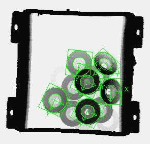
- 2D and 2.5D Position Recognition with VMT® 2D
Position and rotation recognition of objects for vision guided robots.
The core of the system is a neuron network that can be trained to recognize characteristics with the aid of models and trial characteristics. The system’s sensors are therefore able to identify liberal characteristics or contour elements.
By adding further appearance variants, the system achieves maximum recognition capability possible. Fluctuations in the surrounding conditions and varying image backgrounds may therefore be easily optimized.
Through combining approved special sensory procedures on the subpixel level, it is possible to achieve the highest accuracy subsequent to the reliable recognition of characteristics.
The unit is operated with a modern user interface that allows intuitive working. No knowledge of programming at all is required to operate the unit.
Since operation is being kept so simple, two days of training are usually sufficient to be able to operate the system.
Integrated into an automatic sequence VMT 2D fulfills its task reliably. In case of irregularities, it is possible, with the aid of statistics and service tools, to analyze the source of the problem and remove the cause. 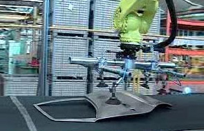
-
- Position dependend control of machining units
- Recognition of objects in liberal rotation (360°) and position. Position identification up to 0.1 mm also with large workpieces with multiple cameras from different perspectives
- Multi-level sensory procedures offer the highest recognition capability, precision and reliability possible
- Recognition of characteristics is trainable for the widest range of object characteristics, object variants and different backgrounds
-
- Automatic image memorizing, therefore short operation startup and time optimizing, as well as error documenting
- The number of the characteristics of a workpiece, for the purposes of recognition and inspection, may be liberally expanded and combined
- The applications are realized with the aid of stationary cameras or robot hand cameras
- Standardized protocolls for all current robot controllers
-
- Fully automated process of robot-aided camera calibration and workpiece referencing
- Validation of workpiece geometry (recognition of inadmissible deviations from characteristics)
- Measuring up to 6 degrees of freedom through combination of several measuring level
Position Recognition 3D
- 3D
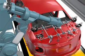
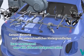
Robot Vision with VMT® 3D
Contactless position recognition of workpieces and subassemblies in 3D space allowing control of handling units, assembly units and robots
The core of the system is a neuron network that can be trained by models of the characteristics to be recognised. The characteristics of the models may be, in addition to holes and edges, of any complexity and structure. This guarantees high flexibility.
By adding further appearance variants, the system achieves maximum recognition capability possible. Fluctuations in the environmental conditions and varying image backgrounds may therefore be gained control of by an easy optimization.
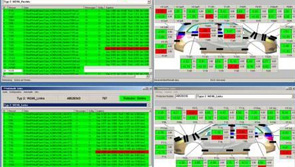
The unit is operated with a modern user interface that allows intuitive working. No knowledge of programming at all is required to operate the unit.
Since operation is being kept so simple, two days of training are usually sufficient to be able to operate the system.
Integrated into an automatic sequence VMT IS fulfills its task reliably. In case of irregularities, it is possible, with the aid of statistics and service tools, to analyze the source of the problem and remove the cause.
-
- Suitable for bare and cataphoretic varnished car bodies, as well as primed and finish-lacquered bodies
- Inspection, supervision, type identification and spray checking with one and the same system
- Simultaneous measuring of several objects with individually calculated object positions for higher processing accuracy
- Quickly trainable to identify the largest variety of characteristics, thus very adaptable to object modifications
- Generates correction data in relation to reference position
- Suitable also for difficult application conditions, such as changing background, etc.
- Reliable measuring, even if a camera fails or a characteristic is covered up
- Plausibility check for verification of measuring results and elimination of collisions
- Measuring of the relative position of components mounted on an object
- Automatic image storage, thus requiring little time for operation startup and optimization
- Gap-free logging of all system activities internally and of the interfaces to unit control and to the robot
- Cyclic measuring of tool geometry on the robot possible (Rob Check)
- Communication with multiple robots concurrently (standard protocols, all manufacturers)
- Protected procedures for simple camera calibration and readjustment, without further auxiliaries
- Optional offline teaching station for preparation of new and optimizing existing models
Robot Guidance
-
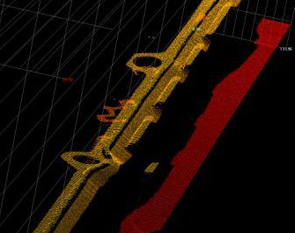
Robot Path Correction with VMT® BK
By means of the VMT BK system for path correction, the robot can accurately follow the actual workpiece contour.
The nominal robot path with its support points is applied to a reference workpiece whose contour is designated as nominal. If a new workpiece is introduced, its contour does not match the nominal robot path any more. By measurement on the actual workpiece con-tour, the path support points are matched to the actual contour. By using the path support points, corrected in this manner, the robot can accurately follow the actual workpiece contour.
In order that the robot is able to measure the workpiece contour, there is a suitable VMT Linerunner Lasersensor installed on its hand. The robot “sees” the workpiece edge with the help of this sensor and can thus determine its relative position on any path support point.
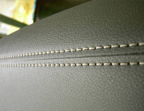
Offline-Path CorrectionApplications - Seam sealing
- Edge processing
- Soldering and welding
- Processing workpieces
Integration into the production process - Measuring and processing in one station.
Advantage: saves space in the line.
- Separate stations for measurement and
processing.
Advantage: No soiling of the measuring equipment, application tool does not need changing.
Method - Measuring run:
In the first step, the processing contour on the workpiece is measured. To this end, the robot guides a sensor along the processing contour.
- Path correction:
Every single support point on the path is corrected on the basis of the measured values.
- Application run:
The robot processes the workpiece using the corrected path.
Many processing tasks require a robot path that is individually adjusted to the piece. Not only the position of the workpiece, but each individual processing point on the workpiece must be measured and the robot path correspondingly corrected. The VMT BK system measures the geometry and the position of the seam/joint/edge with an accuracy of 0.1 mm or better and corrects every individual support point of the robot path. The robot can thus carry out its processing tasks with the highest accuracy. 
-
- Can also be used for processes that are sensitive to soiling because of the delay between measurement and processing
- Fine adjustment of the processing path of the robot is possible without influencing the measuring path
- Measurement of edges with a laser triangulation sensor: robust with respect to variable illumination, surface properties and the background
- Generation of correction values at each support point on the path within the cell or vehicle coordinate system
-
- Autonomous learning of the correct path points and automatic sensor calibration
- Generation of relative correction values with respect to a reference object
- Extensive validation checks for reliable measurement results
- Separate specification of tolerances for each point on the path is possible
- Continuous logging of all system activities internally and at the interfaces to the machine controller and to the robot
- Simple logging for communication with all common industrial robots
-
- Quality control of the local edge geometry can be carried out at the same time
- Controlling of several robots with one system computer
- Referencing of the object’s edge to an arbitrary point: outer corner, inner corner, centre of sheet, etc.
- Reliable calculation of the edge, even if damaged or soiled
- Self-calibrating after sensor replacement without any additional aids
- Optional: compatible with the VMT 3D position detection unit on the same system computer
Bead Control
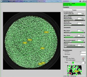
- Inspection of
adhesive applications with VMT® ACS
The core of the system are specially developed methods of testing adhesive beadsand surfaces with rubber applications. Also, the system is able to check for weak-contrast bead applications.
Owing to the integrated position recognition and position tracking, the system ensures accurate position control of adhesive beads. This is possible even with the cameras overlapping and different camera resolutions.
The unit is operated with a modern user interface that allows intuitive working. No knowledge of programming at all is required to operate the unit.
Since operation is being kept so simple, two days of training are usually sufficient to be able to operate the system.
Setting up of the test areas is interactive with few movements of the mouse.
Integrated into an automatic sequence VMT ACS fulfills its task reliably. In case of irregularities, it is possible, with the aid of statistics and service tools, to analyze the source of the problem and remove the cause.
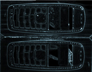
- Detection of interruptions, enlargements, contractions and positional faults
- Suitable for all irregularities and local defects on surfaces where adhesive beads are applied
- Contact-free and damage-free testing immediately after application allows 100% control of all workpieces
- Recognition of position for correction of tested areas when the workpiece is unsteady
- Caliberable metric identification of all measuring parameters, independent of camera resolution or focus direction
- Automatic image saving, thus requiring little time for operation startup, time optimization and error documenting
- Saving of all individual results and test data for subsequent statistical evaluation
- High testing speed
- Application possible with stationary and hand camera robots, as well as combination of both
- Multiple image presentation from multiple cameras
- Display of the defective spot
Best Fit
- Robot position control VMT® RP
VMT RP makes it possible to position a robot gripper equipped with sensors in a defined position with respect to an object, for example, a chassis.
In contrast to the single-step measurement systems, the robot position is adapted continuously with the help of the sensor signals that are recorded.
VMT RP evaluates the sensor signals recorded on the current object and corrects the robot position till the sensor measurement values once again conform to the values of the learning position on the reference object. The robot gripper then once again has the exactly identical relative position to the current object that it had at the time of setting up to the reference object.
Applications- Absolute positioning (form and pierce),
- Relative positioning (gap/transition)
- Assembly tasks
- Parts removal Joining parts through online regulation of the robot
- Precise positioning
- Method
The relative position between the workpiece and a robot gripper is continuously determined using a suitable sensor system.
The sensor data are converted into a position correction value using a mathematical compensation procedure.
A position controller continuously guides the robot gripper until the correct relative position is reached.
- Active positioning
In most processing steps, an add-on piece or a tool must be positioned relative the workpiece.
The constant relative reference point is crucial for successful processing.
The choice of detection points on the workpiece and the robust conversion of this information into a position correction of the tool are crucial for accurate positioning.
-
VMT BestFit Benefits
- Fast positioning through continuously measuring sensors
- Constant manufacturing quality, even for component ageing and temperature fluctuations
- Best possible manufacturing quality for shape tolerances
- Lower cycle times
- Simplest implementation
- Lower setting up, operation, and maintenance times
- Complete process control and documentation
If necessary, dynamic following of a moving workpiece (optional).
Gap Gauging
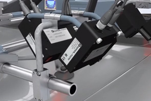
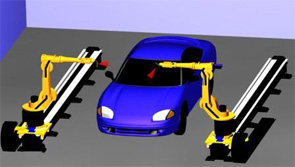
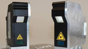
- Gap measuring using the VMT dual head laser sensor
Due to the nowadays very demanding design specifications and related construction options in the automotive engineering industry, gap variations and the flush fit of mounted car body parts has become an even more important quality feature.
Traditionally, such gaps and flush fit dimensions are measured in special “gap measuring tunnels”. These tunnels are equipped with a large number of sensors, because each measuring point requires its own sensor unit.
For this reason the number of sensor units increases very quickly, especially when several, diverse car models are produced in a single production line. As a result, operation and maintenance become very complex, and the acquisition of such a solution requires a very large investment. And when such a solution has been selected, a change in models means a considerable input in regard to adjustments or extensions.
By using the VMT dual head laser sensor a very high degree of flexibility is achieved, which permits a smooth and easy gap and flush fit inspection without any major effort, even on the most diverse car models. A simultaneous inspection of the gap width as well as the flush fit between the mounted parts can be performed on the body-in-white as well as on completed, painted cars in the final assembly stage.
The flexibility of gap measurement is achieved by the pinpoint positioning of the dual head laser sensors by means of industrial robots. This ensures an individual selection at measuring points on the car body without any major installation effort. This applies of course also to measuring points added at a later stage.
In addition to the savings owing to reduced measuring technology, the resulting reduced space requirement - depending on the version - contributes to the efficient deployment of this VMT solution.
The gap measuring cell can be realised in fixed cycle mode as well as in continuous mode.
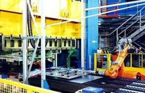
Palletizing / Depalletizing
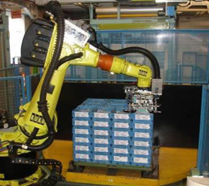
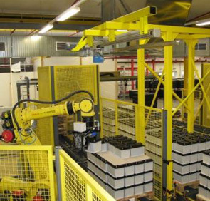
- Depalletizing and palletizing with VMT® D/P
„Bin picking“ is one of the systems with highest interest of the industry, in order to automate the production process, to increase the capacities and to lower the costs.
3D position recognition with laser measurement
Partial solutions exist using classical sensor technology (inductive or ultrasonic sensors) or with the initial stages of image processing.
However a lot of systems have failed in the face of the complex requirements and problematic site conditions. Thus the challenge for VMT consisted of finding a concept that unites the advantages of the individual sensor technologies specifically for each application.
-
The VMT IS system enables very different sensors or sensor systems to be
combined and to extract the necessary information by means of proven
evaluation procedures, so that reliable systems can be offered, which ensure
the highest possible availability.
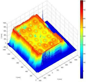
The system is based on 3D evaluation by means of camera technology and/or a height image for the controlling the robot grippers generated by measuring the runtime of the light. However a minimum organization of parts to be recognized and detailed, individual case studies remain absolutely necessary, if the high requirements for the installations availability and profitability are to be ensured.
The requirements for palletizing and depalletizing items from containers or pallets and the handling of parts and various bundles are very complex.
-
The substantial challenges of these tasks are:
- Item complexity and variability
- The very different surfaces of the objects to be processed
- Recognition of containers, intermediate layers, where applicable, and also foreign objects and disruptive contours
- Exclusion of external light interference
- This kind of sensor technology provides not only
significant freedom from external light interference for the testing process
but also the requisite speed, and fulfills the requirements for accuracy.
Additional information is also available for determining, for example, the
stack height and recognizing foreign objects; this is often not available
when using traditional image processing.
The VMT system provides the capability of linking the most appropriate sensors for the variety of individual requirements to the VMT software, in order to generate the optimum solution for the problem. In addition to the image-processing sector (typically surface and line cameras), it also covers triangulation and laser light-section sensors and laser time-of-flight sensors and the latest generation of ultrasonic sensor technology.
VMT Special Solutions
- Special jobs require special solutions.
Irrespective of whether the inspection of fibres in the µm-range or the measuring of rotor blades for wind power plants is required ...
One of VMT's strong points is the ability to offer a great bandwidth of special solution vision systems by combining already existing VMT standard systems and components.
The use of diverse sensor families, derived for example from camera technology and laser technology, as well as of software packages designed specifically for the job in question makes it possible to develop efficient solutions despite not always common, everyday requirements.
If necessary, VMT also offers the mechanical devices that may be required for the vision systems, for example process and turning devices, in cooperation with our long-standing partners from the mechanical engineering industry.
Especially for such tasks, VMT enables its customers to test the potential solution in advance by means of feasibility studies and/or preliminary inspections on the basis of corresponding test set-ups in the VMT Technical Center.